Approaching the ideal
Pipe bundles with vanes increase the heat exchanger surface many times on the oil side
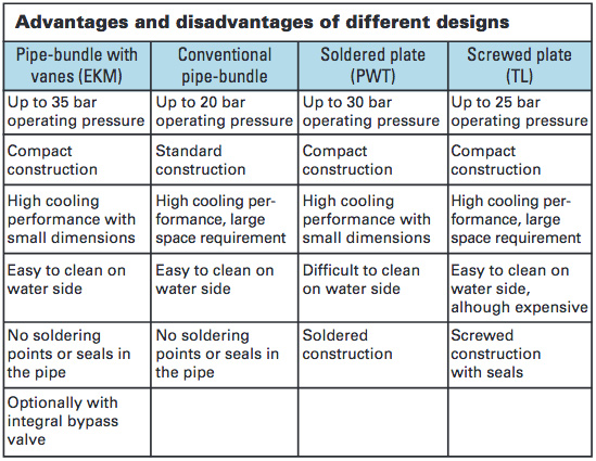
 Plate or pipe-bundle heat exchangers - this is a question often decided by designers in favour of the former, due to
the compactness that can be achieved. But this supposed advantage no longer comes into the balance, thanks to the development of a pipe-bundle heat exchanger with vanes.
The market offers two heat exchanger designs for the oil/water cooling of hydraulic systems, which have come
Design: Standard smooth-pipe heat exchangers
The pipe-bundle heat exchanger (CM, AM series) consists of an outer pipe, through which the hydraulic oil is fed, together with a bundle of thin, smooth pipes, fitted inside the outer pipe. The cooling agent flows through this bundle of pipes. The outer pipe is normally made of steel (or optionally stainless steel), while the pipes in the pipe bundle can be made of Cu, Cu-Ni (90-10) or also of stainless steel 1.4401 (316). Within the outer pipe, the hot oil or other medium is fed past guide plates, in order to improve the heat transfer process. The separating distance of the guide plates can be varied. The result: greater pressure loss at a lower separation distance, while at the same time improving heat transfer efficiency. In addition, different types of end covers can be used on the cold (water) side. The water flows through either once (in which case in is strongly recommended that the water flows in the opposite direction to the oil) or two or four times. The last two methods give a clear saving in the amount of water used, and also slightly improve the cooling performance. Fundamentally, pipe-bundle heat exchangers can be much more easily cleaned on the water side than plate heat exchangers, by removing the end cover. Some manufacturers use so-called ribbed pipes on the cooling side, in order to improve hear transfer efficiency. This design however does not produce the same level of efficiency as the pipe-bundle heat exchanger with vanes.
Design: Pipe-bundle heat exchangers with vanes
The pipe-bundle heat exchangers (EKM) with aluminium vanes on the outer pipe side, as supplied by Universal Hydraulik, work more efficiently than normal pipe-bundle heat exchangers. These heat exchangers have a heat exchange surface many times greater than that of conventional pipe-bundle heat exchangers on the oil side. This in turn allows the more compact design of the heat exchanger (see layout diagram). The aluminium vanes are thereby drawn over the water pipes at a close distance and mechanically expanded. The separators on the vanes also increase the turbulence - thus producing optimum heat transfer characteristics. The EKM series is therefore just as compact as a plate heat exchanger, although it offers further benefits. For instance, the pressure resistance, at 35 bar, is higher than with plate heat exchangers or conventional pipe-bundle heat exchangers. The result: installation in the return circuit of the hydraulic system is considerably less "dangerous" than with other types of heat exchanger. Since the pipes are welded and the water pipes are rolled in, they demonstrate practically no leakage problems. Furthermore, an optional (patented) internal one-way valve is available for the EKM series. The advantage: this saves a further external valve, together with the relevant piping.
For very high cooling performances and high oil throughflow volumes, the larger ECM series is available, while similar requirements can also be met by the connection of multiple heat exchangers, as also available within the product range. Another space-saving version is the EKTM model, designed for installation within tanks.
Design: Plate heat exchangers
Plate heat exchangers are also more compact in design than conventional pipe-bundle heat exchangers. In this design, the media flow between several stainless steel plates arranged one behind the other. The plates are stamped, so that narrow flow channels are formed between the plates. This leads to a severely turbulent flow, resulting in good heat transfer efficiency.
Design: Soldered plate heat exchangers
In the case of soldered plate heat exchangers, the plates are soldered together by means of a copper or nickel coating. This enables economical series production. However, the narrow channels between the plates result in a greater loss of pressure than with pipe-bundle heat exchangers. In the case of larger volume throughputs, this often demands a large number of plates, in order to reduce the pressure loss.
In addition, the channels between the plates can easily become blocked in the event of poor preparation or treatment of the cooling water used. The result: progressively deteriorating performance of the plate heat exchanger. By reason of their design and construction, soldered plate heat exchangers can also only be cleaned with difficulty, and often have to be replaced when they become blocked. The use of plate heat exchangers is always recommended in case of small temperature differences.
Design: Screwed plate heat exchangers
In the case of screwed plate heat exchangers, the plates are suspended in a frame and connected together by means of two pressure plates. This means that the plates are easy to dismantle, the heat exchanger can be cleaned easily, and can also be extended if required by the installation of further plates.
The performance of screwed plate heat exchangers with respect to pressure loss and heat transfer efficiency can be optimised by means of different stamping patterns. However, screwed plate heat exchangers only become economically viable in the event of greater cooling performances, due to their higher basic costs (frame and mounting).